Analysis
Frame Analysis
Substructure uses a state-of-the-art three-dimensional frame analysis. The structure is modeled as straight lines using nodes and members.
Nodes and members are assigned physical properties to simulate the real structure. If there is a tapered member, the sizes of the start section and end section are averaged to obtain the average size for this member. The remaining properties, such as section area and moment of inertia for a tapered member, are computed based on the calculated average sizes. Analysis is done to the top of the footing excluding any footing depth.
Analysis is done to the top of the footing excluding footing thickness.
Columns are set to be fixed at bottom unless a drilled shaft or spring matrix is defined. For defined spring matrix, program will compute nodal deformations for the dof in which springs are provided.
Truss Analysis
Substructure uses a two-dimensional truss analysis. To produce a stable truss structure, every truss member must be connected into triangles (STM only).
At least two supports must be provided. One is restrained in global X and Z direction. The second one, with a larger node number, is restrained only in global Y-direction. The truss analysis is only used to obtain the axial force in each member.
Strut-and-Tie Model
In AASHTO LRFD, you can use the strut-and-tie model (STM) as an alternative analysis tool. Note that in Substructure, the STM is only available for hammerhead piers and isolated pile caps. After the STM is constructed, the truss analysis is used. There are two options available to construct STM:- Manually input the X and Y coordinates for nodes and members.
- Use the mouse to draw the model directly on the screen.
Substructure assumes that strut-and-tie locations will be the centroid of provided reinforcement.
Once the STM is constructed, these locations are well-defined; therefore, you cannot modify the distance between the edge of the cap to centroid of reinforcement (Bar Dist field). To get results for tension tie, you must use the auto design feature since it is assumed that the resistance of the concrete strut is adequate. You can manually add the reinforcement on the compressive side (concrete strut).
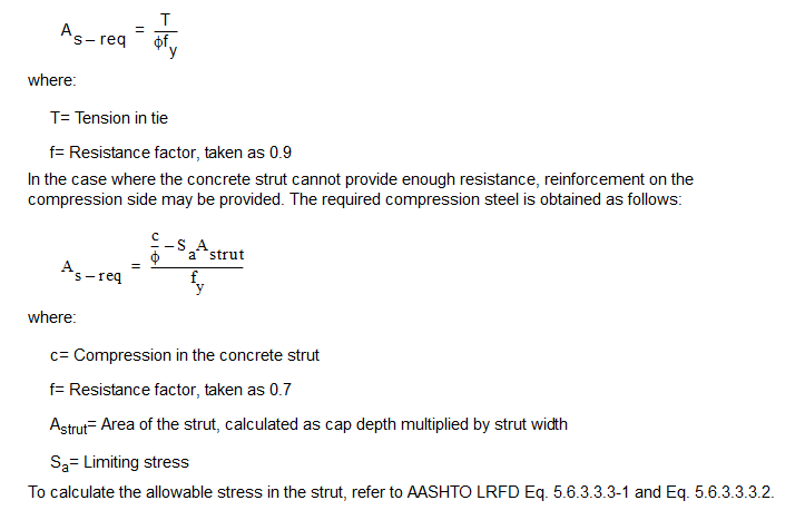
The required steel area for the tension is calculated as:
Where:
T = Tension in tie
f = Resistance factor, taken as 0.9
In the case where the concrete strut cannot provide enough resistance, reinforcement on the compression side may be provided. The required compression steel is obtained as follows:
Where:
c = Compression in the concrete strut
f = Resistance factor, taken as 0.7
A strut = Area of the strut, calculated as cap depth multiplied by strut width
S a = Limiting Stress
To calculate the allowable stress in the strut, refer to AASHTO LRFD Eq. 5.6.3.3.3-1 and Eq. 5.6.3.3.3.2.
When auto design is done, program computes required area of steel in horizontal and vertical ties. However it only computes the required area for vertical ties but does not design stirrups/spacing.
There are many situations that would require the design of a cracked member. For example, if you design a column with its section 30% cracked, you will need to adjust the member section properties in order to simulate the cracking effect.
With this regard, Substructure allows you to reduce the moment of inertia of any members. When you define the cap and column geometry, specify the Factor of Reduced Moment of Inertia (MI). By default, this factor is one. However, for a cracked member, you can specify the value equal to or less than one. For instance, if you input 0.75 in the Factor of Reduced (MI) field, Substructure will use 75% of the moment of inertia of the original section without cracking in the frame analysis.
Substructure can perform analysis and designs under service load (working stress design) according to AASHTO Standard. Service load design is only enabled if you exclusively select the service load group without any factored load group. The service load design provided by Substructure is in accordance with AASHTO LFD Art. 8.15.
When analysis is done for AASHTO Standard service groups only, program generates two sets of envelopes on analysis tab. Envelop N/O is the envelope which does not consider the overstress allowance. For all combinations in which overstress allowance is more than 100%, program divides the force/moment effects by the corresponding overstress factor and then compares and generates the envelope.